Skip to content


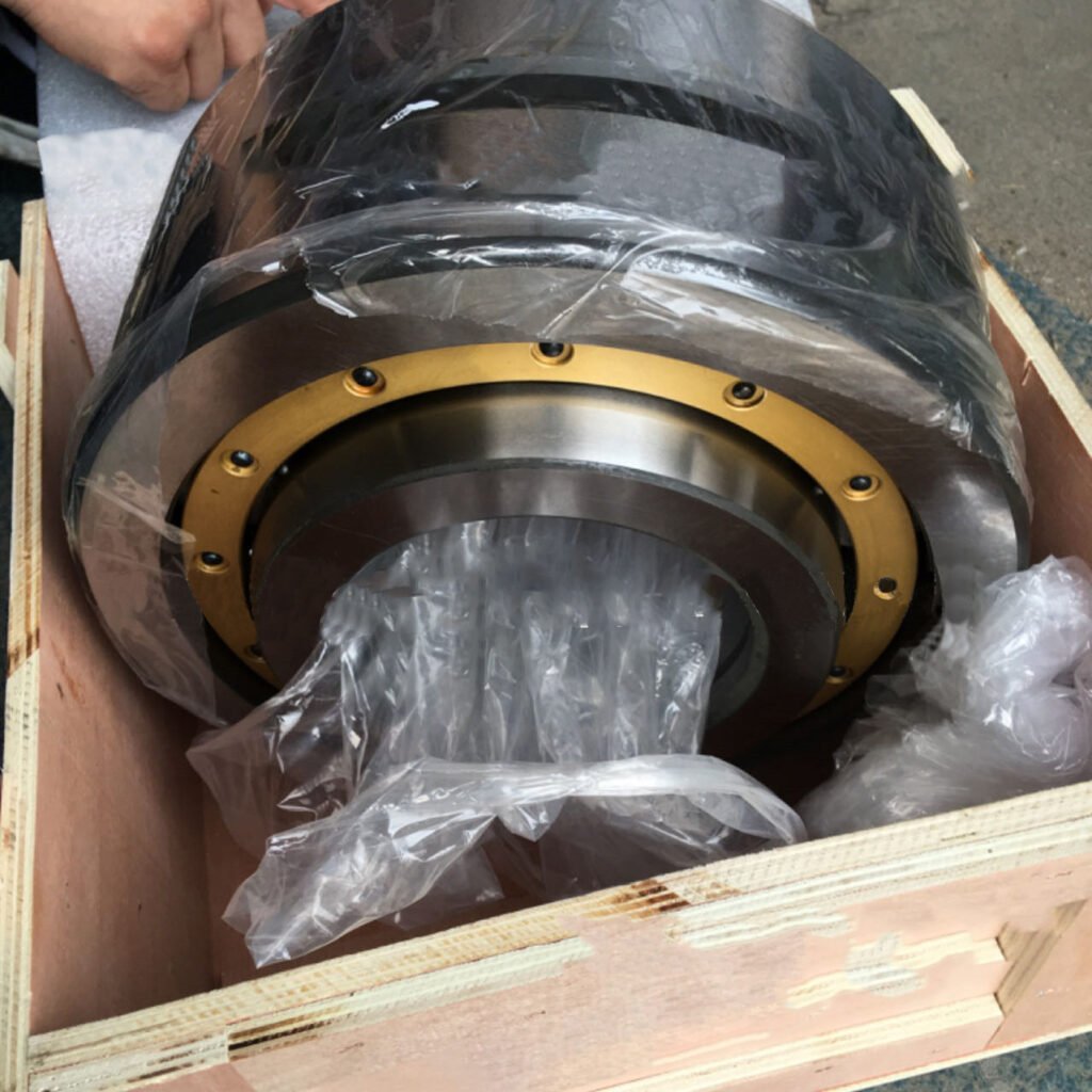
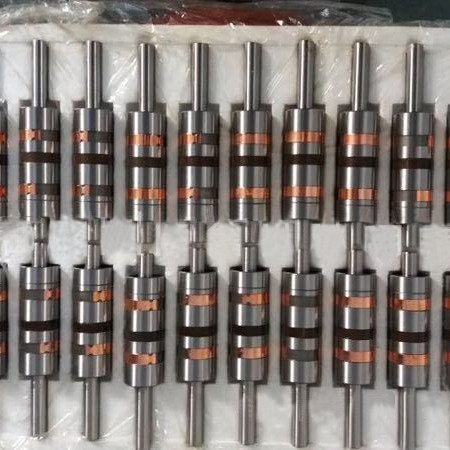
In CNC milling machines, bearings play a critical role in ensuring precision, stability, and production efficiency. Correct installation and disassembly are essential not only for maintaining machine performance but also for extending equipment lifespan and minimizing downtime.
This professional guide provides a detailed overview, including the types of bearings commonly used and their specific installation requirements.
Why Proper Handling of Bearings Matters
Bearings are high-precision components that directly affect spindle performance, machining accuracy, and overall reliability. Improper installation or removal can result in:
Internal damage and premature wear
Decreased machining accuracy
Increased operational noise and vibration
Higher maintenance costs and production downtime
Mastering the correct techniques protects your investment and ensures consistent high-quality output.
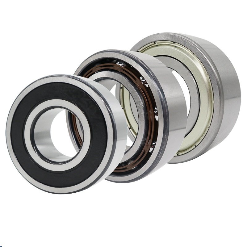
Types of Bearings Commonly Used in CNC Milling Machines
Different applications within CNC milling machines demand different bearing types. The most commonly used include:
Angular Contact Ball Bearings
Used in high-speed spindles.
Handle combined radial and axial loads efficiently.
Often arranged in pairs (back-to-back or face-to-face) for enhanced rigidity.
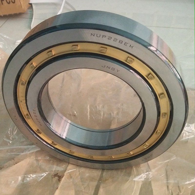
Cylindrical Roller Bearings
Suitable for applications requiring high radial load capacity.
Often used for intermediate spindles or gearboxes.
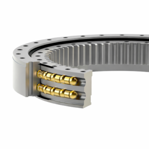
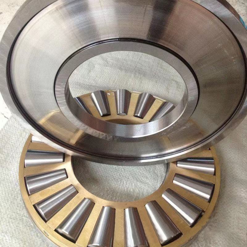
Tapered Roller Bearings
Designed for heavy-duty spindles subject to significant radial and axial forces.
Thrust Ball Bearings
Handle pure axial loads; occasionally used for specific spindle designs.
Hybrid Ceramic Bearings
Feature ceramic balls and steel rings.
Offer higher speed capabilities, reduced friction, and longer service life.
Each bearing type is selected based on the spindle’s speed, load requirements, and precision demands.
Are There Directional Requirements During Installation?
Yes, many bearings — particularly angular contact ball bearings and tapered roller bearings — have specific directional installation requirements:
Angular Contact Ball Bearings:
Have a defined “load direction.
Must be installed with the marked side (usually identified by an arrow or notation) facing the load direction.
Incorrect installation can lead to loss of axial load-bearing capacity and early failure.
Tapered Roller Bearings:
Must be installed in such a way that the large end of the taper faces the load direction.
Tip: Always refer to the manufacturer’s documentation for the correct orientation before installation.
Incorrect directionality during assembly can significantly affect machine precision, bearing lifespan, and operational safety.
Tools Required
Prepare the following specialized tools before starting:
Bearing pullers (hydraulic or mechanical)
Bearing heaters (induction heaters preferred)
Clean, lint-free gloves
Micrometers and dial indicators
Soft-faced mallet
Torque wrench
Anti-corrosion oils and clean cloths
Reminder: Always operate in a clean, dust-free environment to prevent contamination.
Installation Steps
1. Inspection Before Installation
Confirm the bearing model, dimensions, and condition.
Check for dust, rust, or physical damage.
Verify shaft and housing tolerances using precision measurement instruments.
2. Preheating (for interference fits)
If an interference fit is needed, heat the bearing uniformly to 80°C – 100°C using an induction heater.
Avoid open flames or uncontrolled heating methods.
3. Direction Check
Confirm the correct directional orientation of the bearing based on load direction and manufacturer markings.
4. Mounting on Shaft
Slide the heated bearing smoothly onto the shaft to its proper seating position.
Apply uniform pressure on the inner ring only using a specialized mounting sleeve.
Important: Never transmit installation force through the rolling elements.
5. Securing the Bearing
Tighten lock nuts or washers according to specified torque values.
Reconfirm spindle run-out and alignment with dial indicators.
6. Assembly into Housing
Carefully fit the bearing’s outer ring into the housing, ensuring no tilt or misalignment.
Disassembly Steps
1. Preparation
Fully power down and lock out the CNC machine.
Disassemble surrounding components that obstruct access.
2. Loosen and Remove Fasteners
Carefully remove locking devices.
Document or mark the original bearing orientation if planning to reuse.
3. Extract the Bearing
Use a mechanical or hydraulic puller to apply steady and even pulling force.
Avoid jerking or angular force during extraction.
Pro Tip: Slightly heating the housing can facilitate easier removal.
4. Post-Removal Handling
Inspect for signs of wear such as pitting, discoloration, or cracks.
Clean reusable bearings carefully or properly dispose of damaged ones following industry standards.
Common Mistakes to Avoid
| Mistake | Consequence |
| Hammering the bearing into position | Micro-damage leading to premature failure |
| Ignoring directional installation | Loss of load capacity and spindle misalignment |
| Operating in dirty environments | Contaminants causing scoring and accelerated wear |
| Overheating bearings during mounting | Loss of material hardness and structural integrity |
| Reusing damaged bearings | Increased vibration and decreased precision |
Conclusion
Correct installation and disassembly of CNC milling machine bearings are critical to sustaining the performance, precision, and lifespan of your equipment.
Understanding bearing types, respecting directional requirements, and following professional handling techniques significantly reduce downtime, improve machining accuracy, and protect your operational investments.
Invest today in mastering these essential skills — your machines and your customers will notice the difference.
Please click on the link below to read my other blog article “Misunderstandings in Bearing Installation” to help you avoid unnecessary mistakes during bearing installation.